DIY RF Power Amplifier: A Hands-On Guide for Ham Radio Enthusiasts and Electronics Hobbyists
Hey everyone! If you're into ham radio, QRP rigs, or just love tinkering with RF projects, you've probably dreamed of cranking up your signal without spending a fortune on commercial gear. That's where a DIY RF power amplifier comes in. It's one of the most satisfying builds you can tackle at home—boosting a low-power transmitter from a few watts to 10, 50, or even 100+ watts while learning tons about impedance matching, heat dissipation, and RF safety along the way.
I've built a few over the years, starting with a simple single-transistor design on my workbench. Today, I'll walk you through everything you need to know to get started with your own DIY RF power amplifier. We'll keep it practical, beginner-friendly, and focused on real-world results. Grab your soldering iron, and let's dive in!
What Exactly Is a DIY RF Power Amplifier?
In simple terms, an RF power amplifier takes a weak radio-frequency signal (from your transceiver or exciter) and amplifies it to a much higher power level so it can travel farther or punch through interference. Think of it as the muscle behind your antenna.
Unlike audio amps, RF versions operate at high frequencies (HF, VHF, UHF) and must maintain linearity (for SSB/CW) or efficiency (for FM/digital modes). The best DIY RF power amplifiers are custom-tuned to your favorite bands—whether that's 40m for casual ragchewing or 2m for local repeaters.
Why Go the DIY Route?
- Cost savings: A commercial 100W amp can run $300–$800+. Building your own? Often under $50 for a basic 10–20W version using common parts.
- Learning goldmine: You'll master toroid winding, biasing, matching networks, and why your amp might oscillate at 3 a.m.
- Customization: Tailor it for specific frequencies, power levels, or even add bias control for clean SSB.
- Community fun: Share your build on Reddit's r/amateurradio or QRZ forums—folks love seeing homebrew gear on the air!
Key Principles: Amplifier Classes for DIY Builders
Most DIY RF power amplifiers fall into these classes:
- Class A: Super linear but inefficient and runs hot—great for low-power experiments.
- Class AB: The sweet spot for SSB/CW—good linearity with decent efficiency.
- Class C: High efficiency for FM/CW but not linear (distorts voice signals).
- Class D/E: Modern switching designs for ultra-efficiency, but trickier to build.
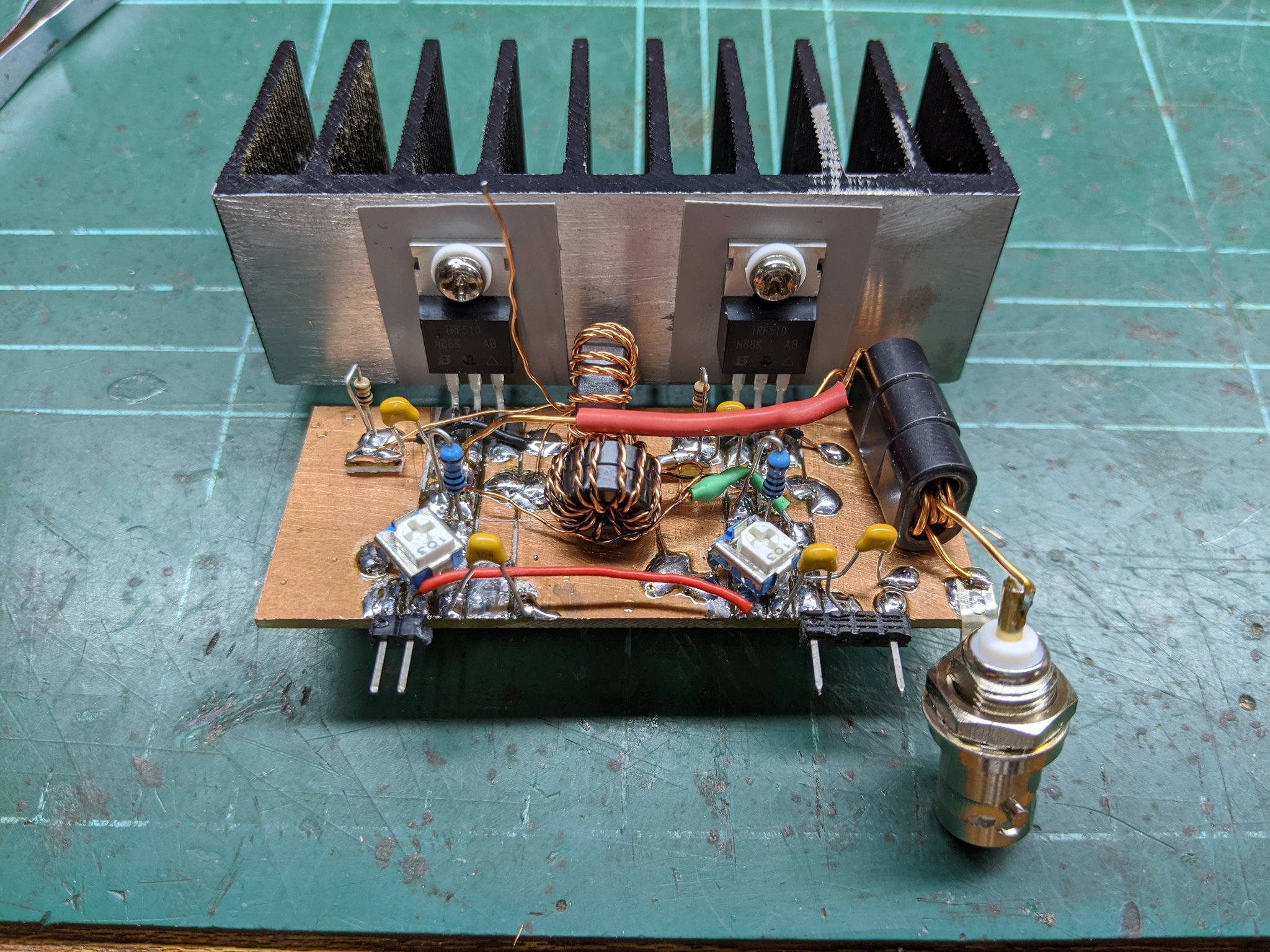
For most hobbyists, start with a Class AB design using a popular MOSFET like the IRF510 (cheap, forgiving, and handles up to ~50W on HF with proper cooling).
Essential Components You'll Need
Here's a basic shopping list for a 10–20W HF DIY RF power amplifier:
- Transistor: IRF510 or MRF455 (for higher power).
- Toroidal cores: FT37-43 or T50-2 for output transformers and chokes.
- Capacitors: Mix of mica, ceramic, and variable trimmers (10–100pF).
- Resistors: 1/4W and 2W non-inductive.
- Heatsink: Large aluminum finned type with thermal paste.
- PCB or perfboard, coax connectors (SO-239), enclosure, and a 12–13.8V power supply (at least 5A).

Step-by-Step: Building a Simple 10W HF DIY RF Power Amplifier
Let's build a proven IRF510-based linear amp for 80–10m bands. This design is widely shared in ham circles and delivers clean 8–12W output from 1–2W input.
Parts List (exact values from popular schematics):
- Q1: IRF510 MOSFET
- Transformers: Input 4:1, output 1:4 on FT37-43 cores
- Bias circuit: 10K pot + resistors + 6V zener
- Matching caps and RFC choke
Step 1: Prepare the schematic and layout. Print a clear diagram (search for “IRF510 HF amplifier schematic” for dozens of free versions). Lay out on perfboard or etch a simple PCB.
Step 2: Wind the toroids. Practice makes perfect—10 turns on the input transformer, carefully scrape enamel, and solder.
Step 3: Assemble the board. Mount the MOSFET to the heatsink FIRST (isolated with mica washer). Solder everything else, double-checking polarity.
Step 4: Add bias adjustment. Power up with no RF input—adjust bias for 100–200mA quiescent current. Monitor temperature!
Step 5: Enclose and connect. Put it in a shielded box. Add input/output relays if you want automatic T/R switching.

Total build time: 4–6 hours for a first-timer.
Testing Your Creation Safely
Never transmit into an antenna without testing! Use a 50-ohm dummy load (build one with resistors in oil for high power).
- Hook up your QRP rig, dummy load, power meter, and oscilloscope or spectrum analyzer if available.
- Key up in CW—watch for clean output, no spurious signals.
- Measure gain, efficiency, and heat.

Safety first:
- Use proper grounding.
- Never exceed your license power limits (FCC Part 97 in the US).
- Watch for RF burns—use insulated tools.
- Add fuses and over-temp protection.
Troubleshooting Common Issues
- Oscillations/parasitics: Add ferrite beads, better shielding, or neutralization caps.
- Low output: Check biasing, toroid phasing, or poor matching.
- Overheating: Bigger heatsink + fan, or reduce drive power.
- Distorted SSB: Lower bias or use a cleaner driver.
Taking It Further: Higher Power and Advanced Designs
Once comfortable, scale up to LDMOS transistors (BLF188XR for 1kW+), add band-switching relays, or integrate with your SDR rig. Many builders document 600W+ solid-state amps on YouTube—search for inspiration!
Wrapping Up Your DIY RF Power Amplifier Journey
Building a DIY RF power amplifier is more than a project—it's a gateway to better operating skills and endless experimentation. Whether you're chasing DX on HF or experimenting with digital modes, that first QSO with your homebrew amp feels incredible.
Start small, stay safe, document your build, and share photos in the comments below—I'd love to see what you create! If you hit a snag, drop your questions and I'll help troubleshoot.


Comments
Post a Comment